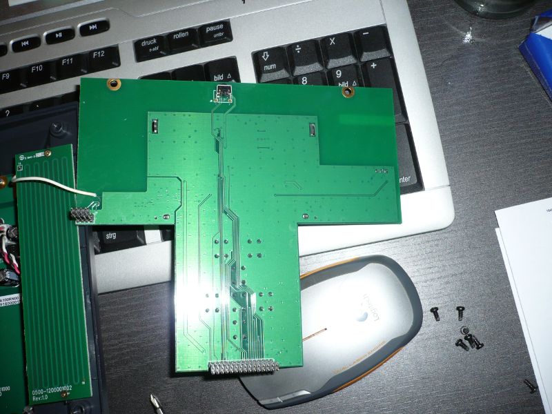
Opened with front panel
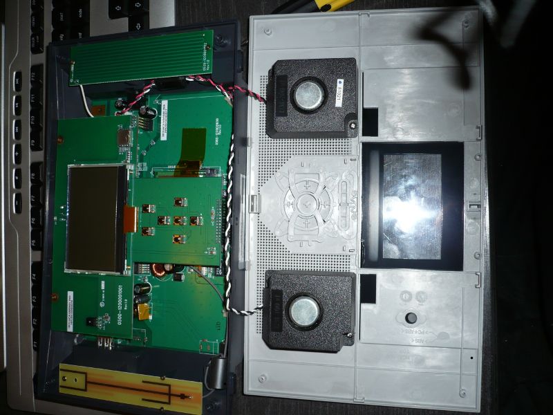
PCBs complete
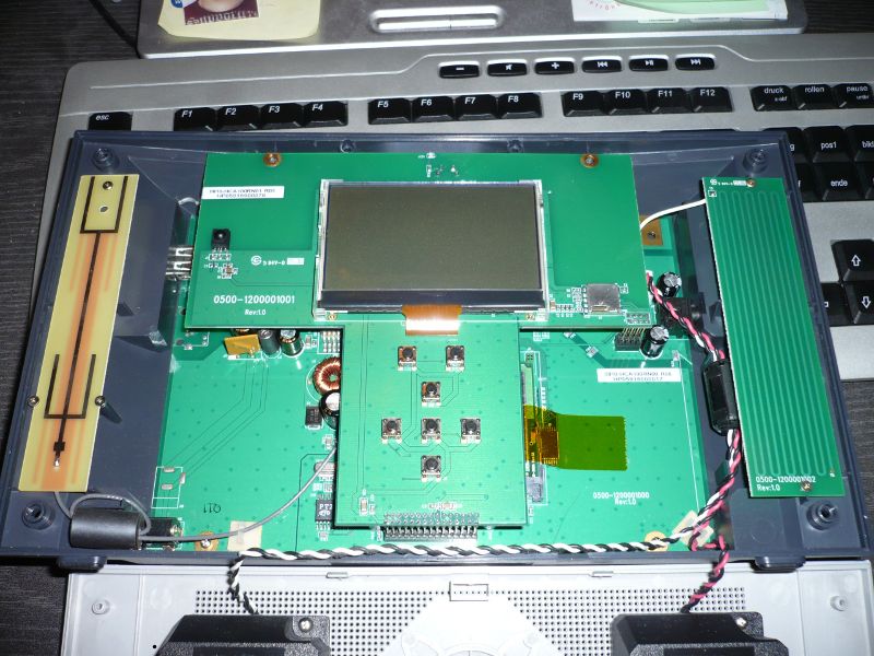
- the yellow PCB on the left is the WIFI antenna
- the green PCB on the right is the FM antenna
- the small metal thingy right of the display is the FM tuner
- the black thingy left of the display is the IR receiver
Main PCB
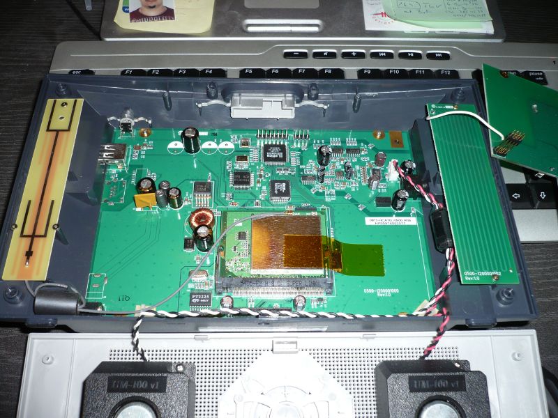
- on the top are two connectors, an 8-pin (J9) and a 4-pin (J5) one
- the 4-pin connector, J5, is the serial console interface, the pins are as follows (left-to-right):
- +5V
- GND
- TxD (from SoC)
- RxD (to SoC)
- the larger ICs are:
- the CPU, a Lattice 4128V CPLD
- a IDT 72V04 L35J FIFO chip
- a Princeton PT8406 MP3/WMA decoder
Back of Front PCB