


A few years ago, I got a Wansview NCH-536MW IP camera. That was one of the first 720p cameras with night-vision, motion and all features you could wish for.

One problem, though: The user interface looks awfully outdated and half of the setup only works in Microsoft Internet Explorer and only if you have some Chinese OCX browser plugin installed. (Compared to Foscam, however, you can at least setup most things without that plugin. With Foscam cameras, you can’t even login if you don’t have their plugin installed.)


While that works, once you have everything set up, it’s always a hassle to change a setting – especially as a Linux user. I need to power up a Windows VM to change anything. And I don’t like that.
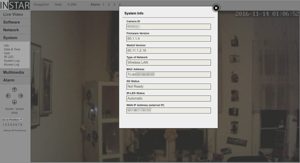
However, the German company Instar developed an awesome HTML5 interface which works like a charm and is cross-browser compatible. It even works from Linux. And you can setup everything without the need for any plugin.
Brothers in spirit (and hardware)
The problem is: There are various different models of IP cameras out there and while they may share the same body, they can have totally different hardware inside. (Camera bodies are re-used amongst companies to not having to spend resources on designing one.)
But luckily that’s not the case with the NCH-536MW. Because the company behind it, Wansview, is also known as Shenzhen Smarteye Digital Electronics Co.. And under the SmartEye branch, they sell these cameras to OEMs. And those OEMs may use the original firmware, or, provide their customers with a customised one.
The hardware I have is sold under these product names:
- Wansview NCH-536MW
- AGASIO A522W (original UI)
- DERICAM H501W (customised UI)
- Foscam FI9820W (customised UI)
- INSTAR IN-6011HD (customised UI)
There’s a HiSilicon Hi3511-compatible SoC with a 16MB Flash memory in it.
Firmwares
Firmware updates come in form of a .pkg file. For the Wansview variant, the latest one is B12SE_V1.4.0.1.9_536mP1.pkg. The INSTAR one is named B12SE_V60.1.1.4_536mP1_60.11.1.2.18.pkg and Foscam’s latest firmware for the FI9820W is B12FC_V3.2.6.1.1_0807Hd9820P1.pkg. (SE = SmartEye/Wansview, FC = Foscam)
If you take a closer look at those files, you’ll notice that they consist of 144 Bytes header data (188 Bytes in older versions) and the rest is a JFFS2 image, around 9-point-something MiB in (compressed) size.
You can get the plain JFFS2 file by running, e.g.:
dd if=B12SE_V60.1.1.4_536mP1_60.11.1.2.18.pkg bs=1 skip=144 of=root.jffs2You can then mount it with these commands (you probably have to use sudo with each of them):
mknod /tmp/mtdblock0 b 31 0
modprobe mtd
modprobe jffs2
modprobe mtdram total_size=32767
modprobe mtdblock

dd if="root.jffs2" of=/dev/mtd0

mount -t jffs2 /tmp/mtdblock0 /mnt/jffs2Code language: JavaScript (javascript)
However, this isn’t much use as we want to get the files onto the camera, not on our desktop PC.
Sadly, the normal firmware updater doesn’t allow files from a different reseller. So we have to find another way. And there is one.
Hardware
If you open up the camera, you’ll notice several unpopulated connectors on the PCB. What you’re looking for is the (mostly) 4-pin console port. A serial port which acts as the main input/output interface to the system. And this is it:
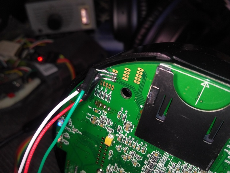
Only 3 pins are important to us: Rx (green), Tx (red) and the GND (white) pin. The fourth is supplying 3.3V which we don’t need.
Once you’ve wired everything correctly and connected the serial adapter to your computer, a new serial port should show up. Connect to it using a terminal program, e.g. minicom or KiTTY. The comm parameters are: 115200 8 N 1, e.g. minicom -b 115200 -D /dev/ttyUSB0. After you’ve set up everything, plug in the camera.
You should see the boot process, U-Boot first followed by the linux kernel. The first few lines look like this:
U-Boot 1.1.4 (Apr  8 2009 - 11:41:01)
U-Boot code: E0500000 -> E0517540  BSS: -> E051E2BC
 HI_VERSION=U_BOOT_1_1_4-M08C0305B0301 @Hi3511v110_OSDrv_1_0_0_7 2009-03-18 20:44:35
RAM Configuration:
Bank #0: e0000000 128 MB
Flash: 16 MB
In:    serial
Out:   serial
Err:   serial
MAC:   00-25-07-00-00-3B
Hit any key to stop autoboot:  0

Memory policy: ECC disabled, Data cache writeback
CPU0: D VIVT write-back cache
CPU0: I cache: 16384 bytes, associativity 4, 32 byte lines, 128 sets
CPU0: D cache: 16384 bytes, associativity 4, 32 byte lines, 128 sets
Built 1 zonelists
Kernel command line: mem=72M console=ttyAMA0,115200 root=1f01 rootfstype=jffs2 mtdparts=phys_mapped_flash:2M(boot),13M(rootfs),1M(setting)
PID hash table entries: 512 (order: 9, 8192 bytes)
Console: colour dummy device 80x30
Dentry cache hash table entries: 16384 (order: 4, 65536 bytes)
Inode-cache hash table entries: 8192 (order: 3, 32768 bytes)
Memory: 72MB = 72MB total
Memory: 71168KB available (1461K code, 175K data, 76K init)Code language: PHP (php)
U-Boot Basics
Notice the “Hit any key to stop autoboot” message. If you press any key at that step, you’ll be dropped into the U-Boot bootloader. That’s where we want to be.
Type help to get a list of supported commands:
hilinux # help

?       - alias for 'help'
base    - print or set address offset
bdinfo  - print Board Info structure
bootm   - boot application image from memory
bootp   - boot image via network using BootP/TFTP protocol
cmp     - memory compare
cp      - memory copy
crc32   - checksum calculation
dhcp    - invoke DHCP client to obtain IP/boot params
echo    - echo args to console
erase   - erase FLASH memory
flinfo  - print FLASH memory information
go      - start application at address 'addr'
help    - print online help
loadb   - load binary file over serial line (kermit mode)
loop    - infinite loop on address range
md      - memory display
mm      - memory modify (auto-incrementing)
mtest   - simple RAM test
mw      - memory write (fill)
nm      - memory modify (constant address)
ping    - send ICMP ECHO_REQUEST to network host
printenv- print environment variables
protect - enable or disable FLASH write protection
rarpboot- boot image via network using RARP/TFTP protocol
reset   - Perform RESET of the CPU
saveenv - save environment variables to persistent storage
setenv  - set environment variables
tftp    - download or upload image via network using TFTP protocol
version - print monitor versionCode language: PHP (php)
Of those, we need three commands: setenv, tftp and erase.
Setting up the TFTP connection
First, we need to setup the connection to the PC. Make sure to connect the camera via ethernet cable to your network. And you need to setup a tftp server on your PC. I used atftpd. For Windows, there’s tftpd32.
Now, we need to configure the IPv4 settings. Use these commands:
setenv ipaddr 172.16.99.9
setenv netmask 255.255.0.0
setenv serverip 172.16.1.2Code language: CSS (css)
ipaddr is the IP address of your camera (or some other unused IP address in your network). serverip is the IP address of your PC (or where your TFTP server is running). And netmask is, of course, the netmask of your network.
Memory layout
The 16M flash memory is located at address 0x34000000 until 0x34ffffff and partitioned like this:
- 0x34000000 – 0x341fffff = boot area
- 0x34000000 is the U-Boot start area
- 0x34100000 is the linux kernel
- 0x34200000 – 0x34efffff = JFFS2 root filesystem
- 0x34f00000 – 0x34ffffff = settings
And yes, the JFFS2 root filesystem is the JFFS2 data from the firmware update files (see above).
Making a backup
If you check the help for the tftp command, its syntax is like this:
tftp address filename [length]Code language: CSS (css)If [length] is given, it will UPLOAD a file to your TFTP server, if it is omitted, it will DOWNLOAD a file from your TFTP server and flash that into the memory.
So, since we know the memory layout, a complete backup of everything but the bootloader (to not risk corrupting it) is as easy as:
tftp 0x34100000 recovery.bin 0xf00000 Code language: CSS (css)This will upload a file named recovery.bin with the linux kernel and JFFS2 image to your TFTP server.
If you should run into problems, you can recover by entering:
erase 0x34100000 +0xf00000
tftp 0x34100000 recovery.binCode language: CSS (css)
Flashing new firmware
If you read until here, it should be clear what to do. After extracting the JFFS2 image file from, e.g. the INSTAR firmware (see above), you just have to put it on your TFTP server to make it accessible to the camera. Let’s say you named it instar.jffs2.
Since we know the memory area for the JFFS2 image, we can first erase it by issuing the command:
erase 0x34200000 +0xd00000This erases the whole JFFS2 memory area, i.e. it sets all bits to 1.
After this is complete, you just have to flash the file from the TFTP server:
tftp 0x34200000 instar.jffs2Code language: CSS (css)That’s it. You can now reboot the camera into the INSTAR firmware:
bootm 0x34100000(This boots from memory at address 0x3410000 – the linux kernel, which will then mount the JFFS2 image and continue booting from there.)
Problems
If you see something like this on bootup of a newly flashed firmware:
jffs2_scan_dirent_node(): Node CRC failed on node at 0x0000000c: Read 0x41c0224d, calculated 0x97e7f5c5
jffs2_scan_inode_node(): CRC failed on node at 0x00000038: Read 0x5a000025, calculated 0x1b754c4d
jffs2_scan_dirent_node(): Node CRC failed on node at 0x0000007c: Read 0x53804006, calculated 0x88f20f93
jffs2_scan_inode_node(): CRC failed on node at 0x000000a8: Read 0x1a180001, calculated 0x05c7cb76
jffs2_scan_dirent_node(): Node CRC failed on node at 0x000000ec: Read 0x130c0000, calculated 0x84df6ac9
jffs2_scan_inode_node(): CRC failed on node at 0x00000118: Read 0xeb290421, calculated 0x5025ee1e
jffs2_scan_dirent_node(): Node CRC failed on node at 0x0000015c: Read 0x00006680, calculated 0x061da826
jffs2_scan_inode_node(): CRC failed on node at 0x00000188: Read 0xaa620051, calculated 0x4e976925
jffs2_scan_dirent_node(): Node CRC failed on node at 0x000001cc: Read 0x91724800, calculated 0x6a08a595
jffs2_scan_inode_node(): CRC failed on node at 0x000001f8: Read 0x10481681, calculated 0xceb194da
jffs2_scan_dirent_node(): Node CRC failed on node at 0x0000023c: Read 0x041c0010, calculated 0x936f78f5
jffs2_scan_inode_node(): CRC failed on node at 0x00000268: Read 0xadab3105, calculated 0x16f7db7a
jffs2_scan_dirent_node(): Node CRC failed on node at 0x000002ac: Read 0x0108e480, calculated 0xc7802b02
jffs2_scan_inode_node(): CRC failed on node at 0x000002dc: Read 0x13e23050, calculated 0xb31f5628
jffs2_scan_dirent_node(): Node CRC failed on node at 0x00000320: Read 0x0005c825, calculated 0x9bdee4df
jffs2_scan_inode_node(): CRC failed on node at 0x0000034c: Read 0x44643000, calculated 0xc2233f22
jffs2_scan_dirent_node(): Node CRC failed on node at 0x00000390: Read 0x0b70408d, calculated 0xd00bb938
jffs2_scan_inode_node(): CRC failed on node at 0x000003c0: Read 0x18509440, calculated 0xe7085f3d
jffs2_scan_dirent_node(): Node CRC failed on node at 0x00000410: Read 0x13400000, calculated 0xac90de05
jffs2_scan_inode_node(): CRC failed on node at 0x0000043c: Read 0x6d822094, calculated 0xd6ce08abCode language: HTTP (http)
This means that you forgot to erase the memory area before flashing a new firmware. Since “flashing” can only change bits from 1 to 0, it runs into problems when there should be a 1 where there already is a 0, e.g.:
  Old data: 0101 0101
  New data: 1100 1100
Flash data: 0100 0100Code language: PHP (php)
Using the erase command resets all bits to 1.